The project(s)
I came across an infra-red (IR) controlled stereo, and I wanted to make it remote-controlled from my PC. Although apparently, this is unnecessary, it is a potentially worthwhile project since IR is everywhere. Later that I wanted to control a robot vacuum cleaner from my PC; the things I learned from this project turned out to be quite useful. I actually chose a cheaper IR-controlled robot vacuum cleaner since I knew I could easily control it with IR from my PC (with the long-term goal in mind to implement also some visual SLAM). This is a short account of where I started and where this project took me. If you are curious about how simple ML can help reverse engineer IR signals using a cellphone camera, read on!
Recording and Analyzing the signal without an oscilloscope
First, I had to figure out how the IR remote works. This post was really helpful. Now that I knew what to look for in the flashing led, I could start thinking about how to record it. I could put together a simple amplifier circuit, but I didn’t have an IR receiver module laying around (after a long time, I bought some IR receivers and transmitters - this makes life much easier, but I liked the challenge of figuring out an alternative way to do that). So I took the fun/faster way out and thought of alternatives.
The transmitted signal
The bottom line is that there is a “command start” part with a long pulse burst of, say, 4 ms and then a series of bits, varying with the complexity of the device and the remote. So a “1” is a 0.6 milliseconds pulse followed by a 0.6ms off, and “0” is a 0.6ms burst in the carrier frequency followed by 0.6ms off (see also the picture in the following). The receiver circuits are surprisingly forgiving on timing, as I figured out later on (they can manage some miss-timings for the transmitted bits). Especially the carrier frequency was not a huge issue to reproduce precisely. The encoding protocol used is a simple Phase-Shift eying (PSK) protocol, also known as Manchester coding. Short note: why wouldn’t one encode more info on the amplitude of the signal, you may ask? Later excursions to radio signals using my software-defined radio dongle, and reverse engineering RC plane transmitters took me to the word of quadrature amplitude modulation (QAM) which is more-or-less what all high-throughput modern radio uses (plus some error correcting tricks).
Sensing with a cellphone camera:
Digital cameras are very sensitive to IR light, and some of them have pretty decent frame rates (at least that’s what I thought). So here is the deal: I record a video in slow motion and fast shutter to avoid blur with the cellphone. Then I pass the video to my PC and extract the flashing patterns to implement them in a micro-controller afterward.
Short side-note/update on camera-based approach:
Actually, after writing this post, I realized that if I set the shutter speed very high on my Samsung S7 phone, I can see the binary code pop out! Here is a picture from the sony remote I managed to get signals such as the following one

And a video showing the patterns from an Optoma remote (the protocol is different and the pattern containing all the data unfortunately non-repeating):
I later discovered while reverse engineering a robot vacuum cleaner’s remote that the non-repeating patterns were due to toggling between the on and off signal (I detail a way to automatically deal with gappy non-repeating signals later in the post). Luckily, the borders of the patterns are pretty crisp.
Why this works is much more interesting, considering that the framerate of the camera is much slower than required to capture the signal. It has to do with the fact that the scanning of the sensor is, in reality, much faster than the “framerate” of the videos. There are two large families of sensors: CCD and CMOS - Samsung S7 supposedly has a CMOS which means that every pixel value is amplified on the spot and then serially sent for storage etc. As described in this very nice video, some rolling artifacts should have been there. What we observe looks like there is a shift register serving the large dimension of the screen, as if the sensor was a CCD sensor. What I think is happening is that the do have a shift register somewhere dealing with the large dimension to deal better with rolling artifacts or for convenient upstream processing. Or they do some upstream processing to deal with rolling artifacts. In any case, finding binary codes from cellphone may work.
Update (2):
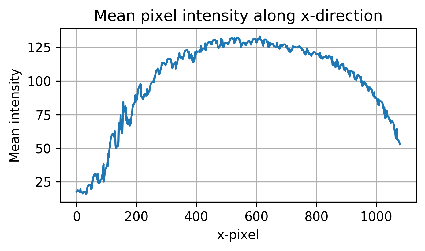
When I started working on the vacuum cleaner project, I still haven’t bought the IR receivers yet. I gave the high-speed IR sensing idea another try. I wanted to do some simple thresholding for the purple light of IR that is sensed from the camera. The idea was to record a video with multiple pressings of the button, align the incomplete signals, and then threshold to get the actual raw IR signal. This worked sort of ok, but with some small additional caveats, I detail below. Firstly, the LED light does not reach the whole screen with the same intensity. In the following, a plot of the mean pixel intensity is shown.
I normalized and thresholded with different intensities according to the pixel position - this left me with a clean binary signal that contained some gaps. I then continued tackling the missing frames issue. I needed a way to align the signals somehow. I was hoping it should be possible to fill in the blanks by summing/averaging. With some simple python code, I aligned the incomplete frames according to the preamble. Alignment was quite easy since the missing frames had the same length and the preamble “on” part was quite large and easy to detect.
At that point, I was hoping that I can average or sum the aligned signals and get the final raw IR signal.
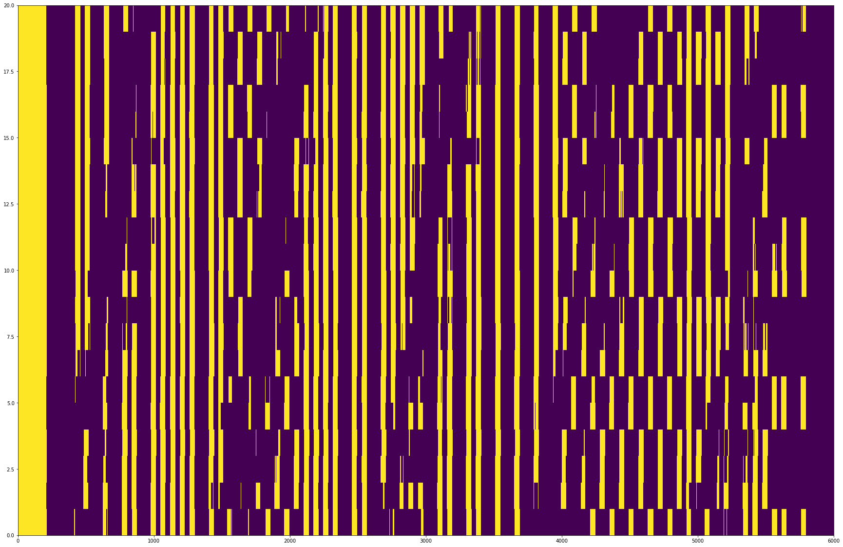
However, a different signal is sent every time a button is pressed for the on-off command. This is the first command I needed to reverse engineer. Here is a plot of some aligned gappy signals that are either on or off commands.
I also figured out a simple way to sort the gaps for easier visual inspection.
Fortunately, it is simple to separate these signals, especially if one considers that they are strictly positive and there are precisely two of them (i.e., the on and off command). I first tried some hand-designed tricks (like figuring out visually what bit belongs to just one signal etc.). Still, I decided to put some simple ML to use to do this more effectively. This can be done by using non-negative matrix factorization. The problem is cast to finding two positive components that explain the signal, and in turn to a matrix factorization problem. The algorithm should discover the two signals (the on and off command) as separate components.
It was easy to cluster the on and off signals in exactly two clusters according to the NMF factor loadings. Here is a plot of the separated signals:
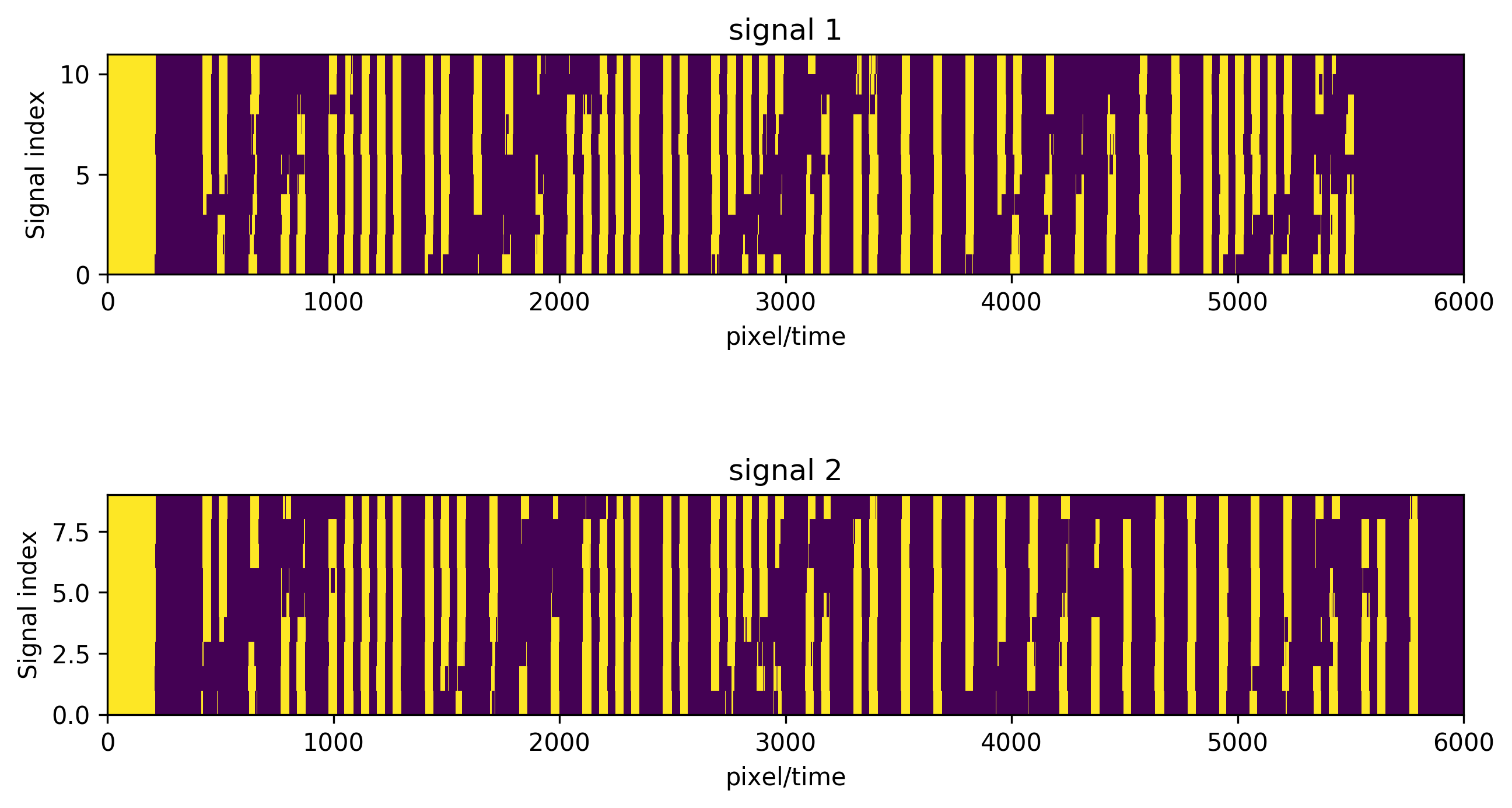
The x-axis is labeled pixel/time because, at this point, I didn’t know how fast exactly was the vertical sensing speed of the cellphone camera. I figured this out by finding some timings from the make eufy smart again project which did something similar for another eufy model (fortunately/unfortunately, the IR codes didn’t match!). I ended up using an IR receiver to get more reliable and accurate results (plus not having to do any video processing).
Sensing with audio input
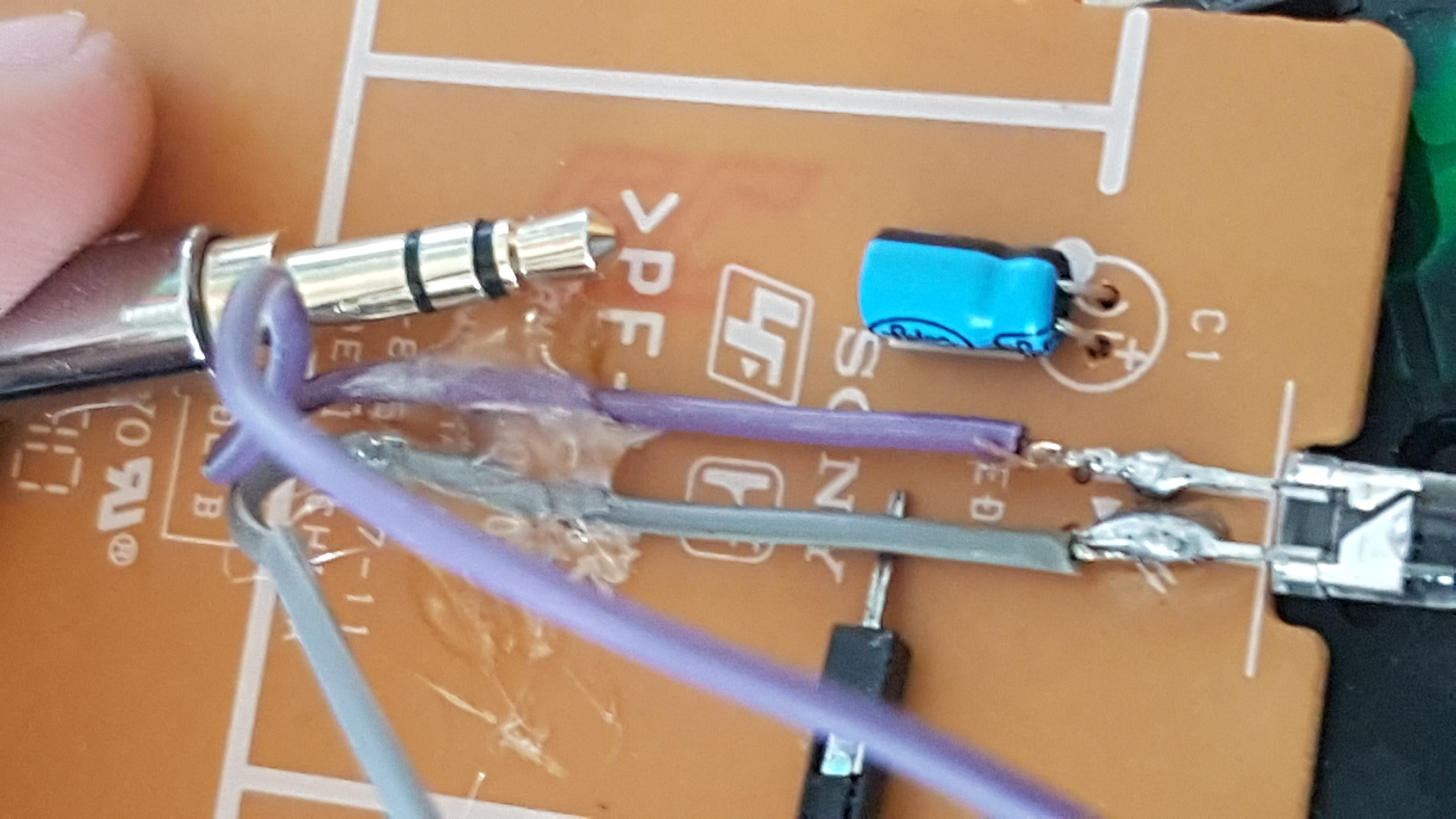
A simple way to record a 44khz electrical signal is simply using the microphone input of your PC. Even if you have a single jack (no dedicated mic input), you can still record audio with a male-male AUX audio cable. Here is the trick:
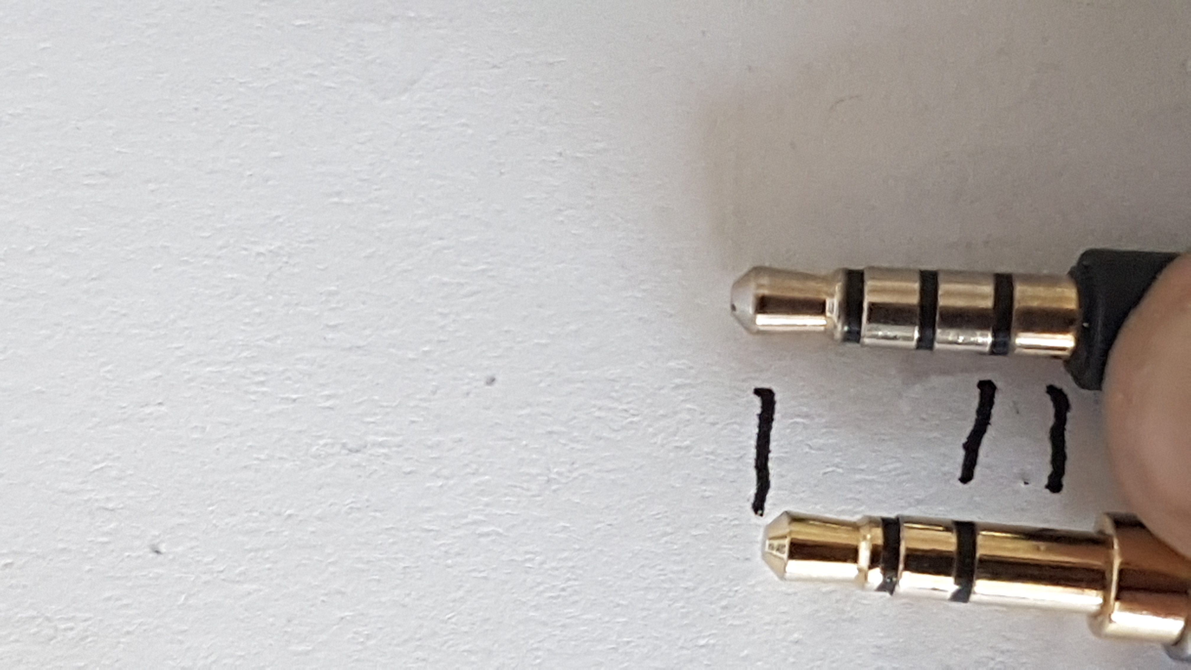
In the picture above, you see a “jack” cable with a mic IO and another one without one. The difference is the first contact part - that’s the mic part! In order to “fake” a microphone to your sound card, you need to put the regular cable partially in your PCs audio IO port. You want the “top” part (which is ground) to contact where it should contact, but the last part of the cable to contact on the part that normally the microphone input would contact.
I wanted to sense the electrical signal directly out of the infra-red LED:
Now I could record directly the signal that the led is supposed to transmit (and maybe some phase distortion from high pass filters in my sound card or something, but this turned out not to be a huge problem). Every time I press a button, a signal that I know more-or-less its parts is going to be emitted from the LED. So now I can use recording software to time the signals. I used Audacity for that
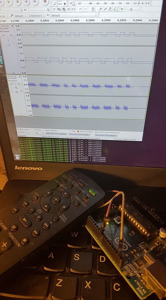
In the image above, you also see the Arduino UNO I used for serial communication and pulsing the LED. Since it was easier for development (and because I didn’t have a decent IR emitter led laying around), I used the remote’s LED for testing my Arduino PWM code. One has to use one of the pulse width modulation (PWM) capable output pins on the Arduino for hooking the cables connected to the remote’s IR led. The same is true when using other micro-controllers (like the wifi-enabled ESP32, which I used for the vacuum cleaner).
Now I had the exact signals to pulse the LED with and control the stereo (at least in principle). The final issue to be dealt with was the inaccurate timing of the PWM output. Although the receiver was pretty forgiving (no stats on that), getting the timings right from the Arduino side was a pain. I was using the delaymicroseconds() and a simple array for the different commands. The Arduino was getting serial signals. I also used this post to pass directly from bash the commands I wanted.
So here is the final result using the stereo:
More on the code
For producing the carrier frequency, you can either use a dedicated circuit with an oscillator or do it by software and rely on accurate timing and a fast dedicated micro-controller. I went with the latter - this is a technique called bit-banging.
The problem with bit-banging is that the timing of the micro-controller is not going to be so reliable (the micro-controller has to do other stuff as well). The timing issues were solved by trial and error: I was running the same code with slightly different delays until the signals in Audacity were matching for 1s and 0s.
The Eufy Vacuum Cleaner “hack.”
Here is a video of the IR controller in action!
The end goal of this project is to also localize the vacuum (for instance, with some simple monocular visual SLAM) and control it from the PC. This is normally ported together with more expensive vacuum cleaners, but I think it’s not difficult to implement. The algorithm should work offline from the PC initially since I can stream the frames of the ESP-mounted camera. Other ways I thought about for localizing the vacuum were audio, floor vibrations, and by checking the signal strength of surrounding WIFI access points. For the audio approach, I would probably I would need 2-3 mics around the house and some training (the vacuum is noisy, so it is audible from the whole house, and imperceptible sound distortions due to the layout should help with localization.)